Lab #2
RC Circuits
This lab is intended to familiarize you with simple AC circuits in the form of RC filters. The purpose is to measure both the amplitude and phase of time-dependent signals in networks with reactive components. The common thread throughout these circuits is the fact that each can be viewed as a voltage divider, but now one of the “resistances” (more correctly an impedance) in the circuit is frequency dependent.
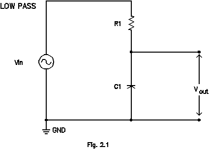
1) Low pass filter - frequency dependent gain: Construct the low pass filter shown below. Let R1=5kΩ and C1=.001mF. First verify qualitatively its performance as a filter, using a sine wave input from the function generator and measuring vout as indicated with the scope. (What do you expect a low pass filter to do?) Then measure more carefully, especially in the relevant frequency range (decide what this means as you carry out the measurements), the gain (actually attenuation, in this case) |vout|/|vin| as a function of frequency over six decades of frequency from 1Hz to 1MHz in 1-3-10-30... steps. Plot the results on both linear-linear and log-log scales. Why is the linear plot relatively useless in this circumstance? For the log-log plot, instead of simply plotting log10(vout|/|vin|) as a function of log10(f), express the ordinate in dB. Find the frequency at which the signal is reduced by 3 dB and relate this to the RC time constant of the circuit. Verify that the slope of the gain (again expressed in dB) vs. log(f) (or log()) is -20dB per decade or -6dB per octave. (All our logs here are base-10 logs since that is the form of log-log paper generally available.)

2) Low pass filter - phase shift: Besides having a frequency dependent gain, this RC filter also causes the output to be displaced in time, or phase-shifted, relative to the input for a pure (single frequency) sinusoidal input. If the input signal is vin(t)=Vincos(t), the output exhibits a phase shift so that the output signal is given by vout(t)=Voutcos(t+). Measure the phase shift, , of the output voltage as a function of frequency. Be sure to describe clearly how you make this measurement. On a dual trace scope you can display both input and output signals together to see the phase shift. Make a plot of vs. log(f) or log() over the same six decade range as was used in the gain measurements.
3) Square wave or transient response: Briefly examine the filter's effect on a square wave input. Sketch the evolution of the shape of vout(t) with frequency over the same six decade range as above, but in decade steps.
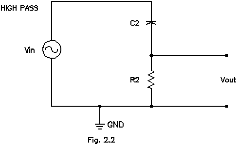
4) High pass filter: Now build a high pass filter as indicated (R2=100kΩ and C2=.001F)and repeat the measurements of gain and phase performed for the low pass filter over the same frequency range. Plot the results. Where's the 3dB point for this circuit? Again examine the the filter's effect on a square wave input. Sketch and summarize in words.

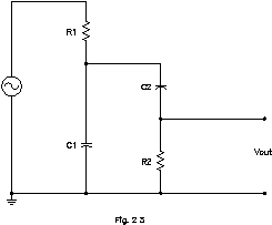
5) Filters in series, loading effects: Combine these filters in series, first low-pass followed by the high-pass. What does |vout|/|vin| look like as a function of frequency? Is there a frequency range or frequency band that this filter passes with least attenuation? If so, relate to the 3dB points of the individual stages.

Reverse the order of the stages. Look at the frequency response again and explain any differences from the previous case. Discuss the loads (impedances) that each filter presents to the other when arranged in the two different orders. What would you need to do in order to make the second configuration a more respectable “band-pass” filter? (Think about each filter as a voltage divider.)
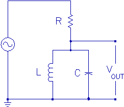
6) Tank circuit: Construct a filter that includes a resistor, capacitor, and inductor, as shown. Use R=470Ω, C=.047F and L=680H. Measure the gain (again, the filter actually attenuates the signal) of this filter. What kind of filter is this: low-pass, high-pass, band-pass, or band-reject (notch)? The parallel LC combination used in this circuit is sometimes referred to as a tank circuit. Which components determine the behavior of the circuit at low frequencies? At high frequencies?
