Now increase the load on the power supply by putting a smaller load resistor (1kΩ) across the output, and record Vout. What's the maximum current flowing through Rload (calculate this from the measured voltage)?
Lab #4
Diodes and Power Supplies
This lab will acquaint you with the use of diodes in constructing DC voltage sources from AC voltages from the power lines. Involved in this conversion are stages for transforming, rectifying, filtering and regulating the output voltage.
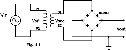
1) Rectifier circuits: Build a full-wave rectifier bridge with the transformer and diodes provided. Transformers are simply two coils of wire “coupled” magnetically. An alternating current driven through the primary coil of the transformer produces a time-varying magnetic flux cutting through the secondary coil, and therefore there will be some emf (electromotive force, or potential difference) induced in the secondary; i.e. there is some mutual inductance coupling the two coils in the transformer. If an external element (e.g. a load resistor) is connected across the two ends of the secondary coil an alternating current will flow through the secondary coil and load as a consequence of the induced emf. The magnitude of the induced emf is determined by the input voltage and the ratio of the number of turns in the two coils. Hence transformers may be used to produce AC voltages higher or lower than that provided at the wall outlet. In this case, a “step-down” transformer is being used.
CAUTION: the transformer is powered from the “line” voltage (120VAC) and is dangerous; be sure not to touch the leads on this side of the transformer. When putting the circuit together also take care to get the polarity of the diodes correct, since if they're installed backwards you can effectively create a short circuit across the output of the transformer, causing a large current to flow, leading to heat, smoke, and a useless unit. First measure the output (or secondary) of the transformer (Vsec),thinking about what's grounded where, before hooking it up to the diode bridge. Use the oscilloscope for this measurement. After building the basic circuit place a 100kΩ resistor across the output to provide a small load on the power supply. Then measure the rectified output of the diode bridge. Make quantitative sketches of these. What's the frequency of the input to the bridge? Of the output?
Now
increase the load on the power supply by putting a smaller load
resistor (1kΩ) across
the output, and record Vout. What's the maximum current
flowing through Rload (calculate this from the
measured voltage)?
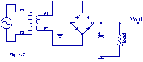
2) Filters: Now try a 22F capacitor placed across Vout and ground (see figure). Observe the polarity markings on the capacitor. Then observe and sketch Vout as a function of the current drawn from the power supply by using Rload = , 10kΩ, 1kΩ, 500Ω, and 200Ω. Plot the peak-to-peak amplitude of the ripple (the AC part) of Vout as a function of the maximum current flowing through the load (Use of AC coupling at the scope input will allow you to block out the DC voltage level and measure the ripple with more precision). Increase the filtering by using a 125F capacitor and again measure (don't sketch) the ripple as a function of the current drawn by the load. Finally, try a 1000F capacitor and repeat. Based on these measurements, make a plot of the ripple voltage as a function of the current drawn by the load resistor for the three different capacitors (all on one graph if possible).
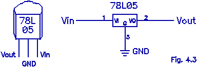
3) Voltage Regulators: These are 3-terminal pre-packaged black boxes that make life much simpler. They're solid state devices that accept a poorly regulated (lots of ripple) quasi-DC voltage and put out a stable, relatively ripple-free voltage of a specified value. The item used here is a 78L05, a +5V output device, rated at 100mA maximum output current. It accepts unregulated (i.e. moderately filtered) input voltages in the rage 7 to 30V DC and cheerfully produces a quiet 5V. There are a great variety of voltage regulators available from standard IC manufacturers, spanning positive and negative voltages and a range of output current levels. The larger the desired current, the larger the device is (usually), due to the increased power demanded of it. In addition, one can find adjustable regulators, for which the output voltage may be determined with an additional, external component (usually a pot).
Try one of these attached to your bridge circuit, inserted between the filter capacitor and the load, and look at the output as a function of current drawn by the load. Again record the size of the ripple under varying loads, being careful to avoid approaching the current limit of the device (use Rload no smaller than 200Ω). Determine how sensitive the ripple is to the size of the filter capacitor. For a load of 200Ω, what approximately is the minimum filter capacitor needed to keep the ripple below 5mV peak-to-peak?