Lab #5
Simple Transistor Circuits
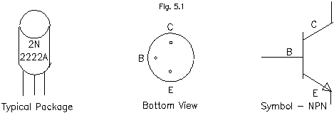
In this lab you will build some elementary transistor circuits. While in the real world, designing circuits at the transistor level is often unnecessary due to the availability of more sophisticated and convenient integrated circuits, transistors are the essential ingredient in all such devices. Design using discrete (i.e. individual) transistors is still an important technique when working with circuits that require high power or high voltage or operate at high frequencies. The transistor used in this lab is a standard bipolar NPN device.

1) Type determination: Verify that the transistor is in fact an NPN type using an ohmmeter,regarding it as two back-to-back diodes. Explain how you do this and report measured resistances.
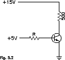
2) Measuring hfe (or ): Recall that for a transistor Ic = hfeIb. Use the basic circuit below to measure Ic for various Ib. Change R to obtain different Ib, using the values R = (5MΩ, 1MΩ,500kΩ, 100kΩ, 50kΩ, 20kΩ and 10kΩ). Describe how you measure both Ic and Ib. From a linear/linear plot of Ic vs. Ib estimate hfe () for your transistor. Also make a plot of log(Ic) vs. log(Ib) (measure both currents in mA for consistency), and determine a value of from this graph as well. The 500Ω resistor between the power supply and the collector is present to limit the collector current.
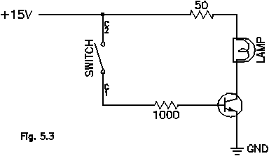
3) A transistor switch and transistor saturation: Verify that with Ib=0 in the circuit below the light bulb is off and that it turns on when the switch is closed. The 50Ω resistor again serves to limit the current to the bulb, otherwise it might burn out. Measure Ib and Ic. Also measure the voltage drop between the collector and emitter of your transistor, Vce. Replace the 1kΩ resistor with 10kΩ, 100kΩ, and 220Ωresistors and repeat the measurements of Ib, Ic, and Vce. Make a plot of Vce as a function of Ic. Where in this plot does transistor saturation occur? From your measurements, estimate the resistance of the light bulb when it's on and when it's off (not glowing).
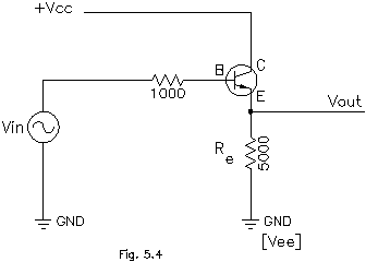
4) Emitter follower: Build the emitter follower shown, using Vcc=+5V and the function generator (2Vpp, 5kHz) as Vin. Be sure that the DC offset of the function generator is off. Use the scope to observe the waveform with the scope input DC coupled. Observe Vout: include quantitative sketches of the input and output. Then vary the amplitude of Vin and report your observations. For what input voltages does “clipping” of the waveform occur?
Try again with Vcc=+5V, but let Vee=-15V, instead of connecting the emitter resistor to ground. Be careful about where you ground the low side of the scope and function generator leads for this case; don't connect them to the emitter resistor. Vary the amplitude and DC offset of the input and observe the output. Quantitatively sketch the input and output for a situation in which there is no clipping and again when there is clipping apparent in the output. Why does clipping occur? Explain the differences in behavior of the circuit for the emitter resistor connected to ground or Vee=-15V.
5) Common emitter amplifier: Build the simple amplifier shown below. Let R1=100kΩ,R2=10kΩ, Rc=5kΩ. Use +12V or +15V for Vcc. Choose Re to give a gain of approximately 10 for the amplifier. Choose Cin to give a 3 dB point for the input of 100 Hz (Make the input act like a high pass filter. The effective resistance for ac signals applied to the input is the parallel combination of R1,R2, and Re - which resistance dominates this combination?). Use Cout=.01F. Estimate what the quiescent current is (Ic or Ie without Vin applied), based on the biasing network of R1 and R2 and the value you chose for Re. Verify your estimate by measuring Ve to find Ie.
Apply a small AC signal (Vin = 0.1Vpp @5kHz) to the amplifier. Use a voltage divider if the output of the function generator can't be made small enough. Make quantitative sketches of Vin and Vout. Is there a phase shift?
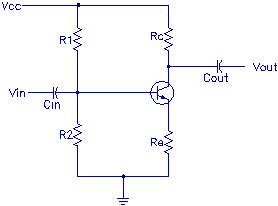
Vary
the frequency over the range 1Hz to 1 MHz (in 1-3-10-... steps) and
plot the frequency response (|vout/vin|
vs. log(f)) of your amplifier. Does it behave as designed?
If you observe deviations, try to explain them. Vary the amplitude
of the input. Do you observe clipping? If so, for what input
amplitudes? For the positive or negative portion of the waveform?
Why does it occur?