Lab #7
Transistor Applications
Today we will build a push-pull follower and a differential amplifier, real-world transistor circuits.
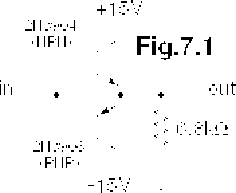
1) Feed the breadboard's built-in speaker with a sine wave from the function generator in the few kilohertz range, listen to the tone. Look at the speaker's specs, and put in a current-limiting circuit so you can't blow the speaker. Be sure the DC offset of the function generator is zero. Build the push-pull emitter follower shown in Fig.7.1. Listen to what this does to the sound output. Use the scope to compare the signal before and after the push-pull circuit, and quantitatively describe the “crossover distortion”. If things behave weirdly, you might have “parasitic oscillations”. Try inserting a 470Ω resistor in series with the common base lead, and/or add a 100pF capacitor from output to ground. Did this help, and if so, why? What was causing the noise? Once things work, play with the input amplitude. What happens and why? What does adding a DC offset to the input signal do?

Try to eliminate the crossover distortion using a pair of diodes to bias the base voltages as discussed in class. When you make a change to a circuit on the breadboard, draw a new diagram in your lab notebook!

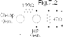
2) Simulate a noisy signal containing a low frequency 250 Hz “noise” of a few volts size, and a higher frequency ~100mV 5000 Hz “signal” summed together. Use the breadboard or other cheapo function generator to make the “noise”, and use one of the nice HP function generators to supply this signal. This is because the output of the HP “floats” - the outer conductor of the BNC cable (the “-” terminal in the figure) is not automatically grounded – so the two signals will add instead of being grounded out by the 2nd generator's socket. See Fig.7.2. Note that a) the voltage you'll see on the oscilloscope is a lot less than the generators would put out with no load; and b) you can't get try to dial up too large an input voltage on either signal or a current limiting circuit kicks in. If things are working right you should get a larger slower sine wave with a smaller faster wiggle superimposed.

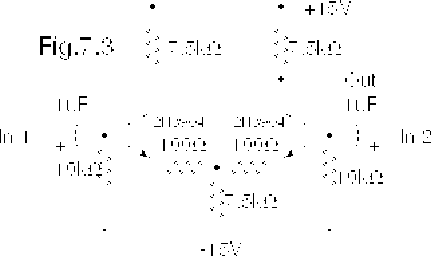
3) Build the differential amplifier shown in Fig.7.3. Measure the common mode gain by driving the circuit without the differential “signal”. Measure the differential gain by dialing down the common mode “noise” amplitude to a minimum. What is the CMRR? Does this match your predictions? What is the circuit's f3dB? Try different amplitudes of the two input signals to see if the output signal is saving the “signal” and rejecting the “noise”.