
Lab #8
Op-amp Circuits
In this lab you will construct a variety of basic circuits using an op-amp. For these circuits use 1% tolerance (precision metal film) resistors.
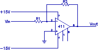
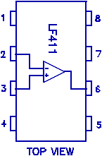
1) Inverting Amplifier: Build a x10 inverting amplifier using an LF411 op-amp. The pin designations are as indicated.


Use R1=10kΩ, R2=100kΩ. G=-R2/R1. Apply a small (0.40 Vp-p, 5KHz) signal to Vin and observe Vout. Sketch your observations. Why is this an inverting amplifier? (Hint: observe both Vin and Vout simultaneously with the scope.) Vary the amplitude and look for clipping. If there is any, for what input amplitudes does it occur? Is this expected? Measure the frequency response of the amplifier from 1Hz to 1MHz (at 1-3-10-30...Hz) for Vin = 0.1V amplitude. Plot the results (gain in dB as a function of frequency).
Add a capacitor (.001F) in parallel with R2. Before measuring the frequency response of this modified circuit, qualitatively describe the expected effects of this added component on the frequency response. Then measure the frequency response under the same conditions as above. Plot the results on the same graph as the previous measurements. Is the observed “3dB” point in agreement with component values? Examine the output when a square wave (10Hz, 1kHz, 100kHz) is applied to the input. What determines the shape of the output?
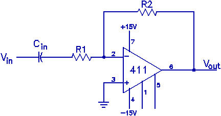
2) AC coupled amplifier: AC couple Vin to the above amplifier with a 0.1F capacitor as shown. Remove the capacitor in parallel with R2. Measure the frequency response of the amplifier again. Does it have a low frequency 3dB point? If so, what determines this frequency? Plot the results. Apply a square wave input at various frequencies (10Hz, 1kHz, 100kHz). What do you observe? What causes these results?

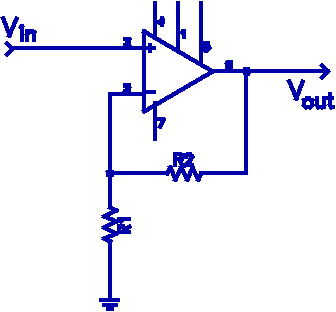
3) Non-inverting amplifier: Construct a basic non-inverting amplifier as shown. Let R1=5k, R2=20k. Before beginning your measurements, determine the expected gain of this circuit. Carry out measurements of the frequency response of the amplifier over the range of 1Hz to 1MHz with a sine wave input of .2V amplitude. Plot the results. Add a capacitor (.001F) in parallel with R2 and re-measure the frequency response. Again plot these results on the same graph as the unmodified circuit. Explain the differences in the two frequency responses.

4) Voltage Adder: Build a circuit that will add two voltages according to the formula Vout=-V1 - 2V2, where V1 and V2 are the two input voltages. Use it to add a dc voltage to a sine wave, mimicking the dc offset control on the function generator. Indicate completely your circuit, justify your choice of components, describe the performance of the circuit, and report any limitations on the amplitudes of the inputs for correct operation of the circuit.