Lab #9
More on Op-amps -- Departures from Ideal Behavior
Real op-amps depart from ideal behavior in two important ways. The output adjusts itself, when negative feedback is in use, so that the two input pins are almost at the same voltage. There is usually a small “offset” voltage between the two inputs, typically a few millivolts. In addition, the inputs will draw (or source) small but not always negligible currents called the input bias currents, ranging from a fraction of a mA down to a few tens of fA (femto=10-15), depending on the particular variety of op-amp. Use metal film resistors in the construction of these circuits.
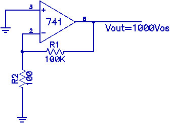
1) Measure the offset voltage (Vos) of a 741 (for many years the standard general purpose op-amp in widespread use) with a circuit such as the one shown in Fig.1. Derive the claimed output expression: Vout=1000Vos, using the golden rules for op-amps and the given component values. Infer Vos from Vout. Be sure to attach nothing else to the inverting and non-inverting inputs other than the components indicated in the schematic. Do not attempt to measure V+ or V- using the scope or DMM.

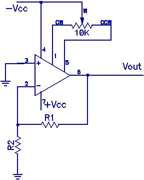
Then “null out” the offset using an adjustable resistor (a trim pot) (Fig.2.) so that the output is as close to zero as possible. How small can you make the output voltage? How stable is it? Examine the output with the oscilloscope to determine how noisy the output is.
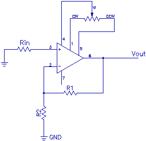
2) Input bias currents: With the offset nulled, measure the input bias current (Ib) using a circuit like the one shown in Fig.3. Infer the value of Ib from measurements of Vout. Again, do not attach any measuring devices to the op-amp inputs. Decide whether Rin should be large or small in order to make the measurement easy. Recall that the input bias current is usually around 100nA for a 741. Explain how this circuit provides a measurement of the bias current. Obtain an expression for Ib in terms of the components R1, R2, and Rin and Vout and evaluate the expression for the specific component values you use.

3) FET inputs: Repeat the above process (measure and null out Vos, measure Ib) using an LF411, which is similar to a 741 except that the inputs are FET's instead of bipolar (i.e. NPN or PNP) transistors. Compare with your results for the 741.

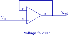
4) Slew rates: The slew rate of an op-amp is the maximum rate at which the output voltage can change. This is determined by the output impedance, internal capacitances, and other "intrinsic" details of the device. External components such as feedback resistances or capacitances, or loads (resistive or reactive) generally reduce the slew rate further. This characteristic limits the response of op-amp circuits at high frequencies. Build a simple voltage follower using a 741. Using a 5V (peak-to-peak) sine wave as input, briefly try frequencies from 1 Hz to 1 MHz (use decade steps) and observe both the amplitude of the output and its shape. At what frequency (roughly) are departures from a sine wave output apparent? Next, make a careful study of the output (amplitude and shape again) for a square wave input (1 Vpp) over the same frequency range. Pay particular attention to the rising and falling edges of the output waveform compared to the input waveform. Compare the observed output with what you would get from a truly ideal (i.e. infinite slew rate) amplifier. From the square wave response of your amplifier at one of the higher frequencies, determine the slew rate of the 741 from what you observe on the oscilloscope.

Take an LF411 op-amp and measure its slew rate in the same way. Compare your measured slew rates with accepted values, found in data sheets.