Lab #10
Assorted Op-amp Circuits
This lab provides an opportunity to build a couple of op-amp circuits and do more than simply characterize the response of the circuits. One is a differential amplifier that can be used to display the I-V characteristics of a diode directly on the oscilloscope. Another circuit produces on oscillating output without any external inputs (aside from DC power, of course). It is an example of positive feedback.
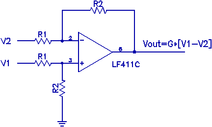
1) Differential inputs: Build a differential amplifier with a gain of 5. Here the use of precision resistors is important in achieving proper behavior in the differential amplification of two voltages. Improved circuits for measuring differences in voltages can be constructed from three op-amps. Such circuits, called instrumentation amplifiers, are commercially available as a complete package in a single integrated circuit. This is a simple one op-amp version. Take R1=10kΩ. Justify your choices of R2. Verify that the amplifier does what it's supposed to do. (Describe the tests carried out!)

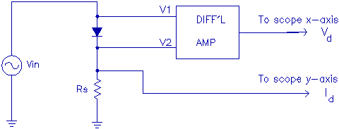
Once the differential amplifier is functioning properly, use this amplifier in a measurement of the current-voltage (I-V) characteristics of a diode, displayed directly on the oscilloscope, using the scope's x-y mode (the x-axis is no longer time). Use some form of the circuit below. Choose Rs to provide 0.1V/mA. That is to say,you want 0.1V output on the “Id” line for every mA of current flowing through the diode-resistor series combination. Remember, the scope senses the voltage at this point, it doesn't measure current directly. The resistor is present to serve as a “current-to-voltage” converter to allow easy display of a voltage that is proportional to the current of interest. Set the oscillator to 4V(p-p). Provide complete details of your circuit, as well as a detailed sketch of the I-V you obtain from the oscilloscope. In your graph of I(V), be sure to label the axes with the correct units, converting the values for the I axis to give the true I-V. Label the axes and scale the scope picture so that you display I in mA and V in mV.

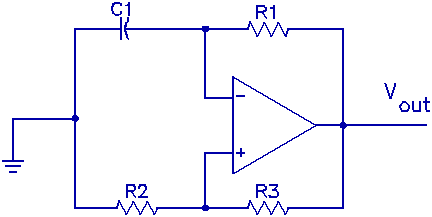
2) Relaxation oscillators: There are a number of ways of constructing circuits that have an oscillating output. One of the simplest is the relaxation oscillator, which itself has a number of implementations. Build the circuit shown. Note that there is no external "input" signal as one expects to find in the circuits constructed so far. Also notice that the output of the op-amp is fed back to both inputs of the op-amp. This clearly isn't a case of simple negative feedback. Let C1=0.01F, R1=10kΩ, and R2=R3=10kΩ.

Measure the frequency of the output waveform. Try capacitors .01, .1 and 10 times the original C1 value and determine the frequency for each case. Repeat with the original capacitor and a wide range of R1 values. Plot the frequency as a function of C1, for the original R1 and as a function of resistance for the original C1. In your report include a clear, qualitative yet systematic explanation of how it comes about that this circuit oscillates.