Lab #11
Simple Digital Gates
This lab is a brief introduction to basic combinational logic gates. It explores the behavior of NAND and NOR gates using LS TTL (low power Schottky, transistor-transistor logic) integrated circuits. It begins with a study of crude logic functions implemented with diodes. It also introduces the use of light emitting diodes as display devices and the use of open collector outputs to drive current hungry devices from logic level signals.
1) Primitive logic gates: Before beginning with “real” gates, build the two diode-based circuits below and measure their truth tables. Instead of putting 1's and 0's in the table, enter the measured voltages of the inputs and outputs. What logic operations do these gates perform?

2) Getting started with TTL: Explore the operation of simple 2 input NAND gates. In wiring logic circuits keep in mind that the integrated circuits used here are not especially forgiving of mistakes made about voltage levels at the power supply connections, inputs and outputs. Think twice before plugging in wires. Double check that you are happy with your connections before applying power. Important points to remember about TTL:
The supply voltage must be +5 volts. DO NOT use the 15V supplies.
The inputs must also be between 0 and 5 volts.
It is essential to take a little extra time to arrange the circuit components so that they can be wired up neatly. The proliferation of wires in digital circuits quickly gets to be a mess and is detrimental to the performance of the circuit as well as making it much harder to find errors. Take the extra time necessary to use jumpers of appropriate length in building your circuits and think about where wires must go before placing components on the breadboard.
Begin by taking a 74LS00 and experimentally verifying that it is a set of four 2-input NAND gates (a “quad two-input NAND”). Use the pinout diagram provided in lab to build your circuits. You need to measure only one gate carefully (i.e. record input and output voltage levels), but verify quickly that the other three function properly. Repeat this for a 74LS08, verifying that it behaves as advertised. Explain how you make your measurements.
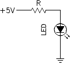
3) LED characteristics: Next take an LED (light emitting diode), a commonly used display device. Experiment with the LED in a simple circuit :

Try R=1000Ω first. What's the voltage drop across the diode? How much current flows through the LED? Does it matter how the LED is installed? Try larger and smaller R's. About how much current must flow for the LED to be just dimly lit?
4) Open collector outputs - driving heavy current loads: LEDs are a convenient way to display digital signals since they can be on or off and clearly you can operate them from a 5V supply. Driving LEDs from TTL can require some care because of the active pull-up outputs of standard TTL gates and some LEDs can demand a fair amount of current. One way around worrying about these details is to use gates with open collector outputs.
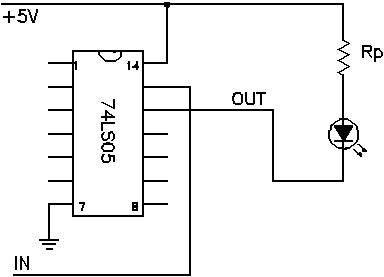
An open collector output is one in which the output pin is really just the collector lead of a transistor inside the IC, left floating or unattached to anything (open). The emitter of this transistor is connected to ground internally. The base of the transistor is driven by a signal derived from the input signal. To use open collector outputs the collector (output pin) is usually connected to a positive Vcc supply (often +5V) through a “pull-up” resistor. When the transistor is off no collector current flows, so there is no voltage drop across the pull-up resistor. This implies that the collector voltage must be the same as the power supply, Vcc. The output is said to be “pulled-up” to Vcc. When the transistor is turned on and driven into saturation by the signal applied internally to the base, the output voltage is determined by the voltage drop from collector to emitter, Vce. Since this is usually about 0.1V, the output corresponds to a logic “low” level. Under this condition there is a collector current flowing from the the Vcc supply, through the pull-up resistor, into the collector of the transistor and out the emitter of the transistor to ground. So, if the gate in use is said to be an inverter with an open collector output, a high input applied to the gate must produce a low output, i.e. the transistor is turned on, driven into saturation, bringing the collector voltage close to ground, and a collector current of approximately Vcc/Rpull-up flows. When the input to the gate is low, the output is high, i.e. the transistor is turned off, the collector is at approximately Vcc and no current flows through the output circuitry. Use a 74LS05, which has 6 inverting buffers with open collector outputs, to run the LED. To use an LED in this configuration, the LED is placed in series with the pull-up resistor as indicated. You still need to include a pull-up resistor; the LED is not a substitute for the resistor. Choose a value of Rp to provide an appropriate current to make the LED visible when on, but not excessive so as to waste power unnecessarily.

Is the diode on or off when your input signal is high or low? Explain why, thinking about the current flow and keeping in mind you're using an inverter and an open collector output stage. Measure voltage levels at appropriate points in the circuit to be sure you understand what's happening. Write down the truth table for this simple circuit, in terms of the input voltage and the LED's state as output.
5) Efficient use of gates in an IC package: NAND and NOR gates are more prevalent than AND and OR gates in building circuits because they are more flexible. It is possible, in designing complex circuits, to need one or two gates of a particular kind. Since most IC packages include multiple gates of one flavor, much silicon can be wasted in the form of unused gates. Clever use of extra NAND and NOR gates allows the synthesis of various other simple logic gates. As an exercise in such efficiency, use a single 74LS00 package to implement the following logic function:
![]()
Measure the truth table. Instead of the tedium of using a voltmeter or scope to measure the output state of the circuit, use the 74LS05 to drive an LED to display the output of your circuit visually. Be sure to get the correct correspondence between the LED state and whether or not Y in the above expression is high or low.