Lab #13:
Timers
1) Primitive Counters. Take the 74LS107A IC (A dual JK flip-flop) you looked at last lab. The pinout is on the data sheet in the manila folder. Tie the J and K inputs high to force the “toggle” mode. Feed the function generator's SYNC pulse into the CLK input, and observe the Q output. Sketch the two. How does the output frequency compare to the input?
2) Make a divide-by-four circuit using both the JK FF's on the '107. Use a ripple counter configuration where Q from the first FF clocks the second. Show a schematic of this. Display the two Q outputs with LED's. Remember to use pull-up resistors to power the LED's, since the open-collector outputs of the '107 don't have the juice to drive an LED on their own. Verify that the lights count from 0 to 3 in binary.
Use a second 74LS107A to add two more FF's to the counter, making a divide-by-16 circuit. Display the 4 output bits with LED's. Verify the counting sequence, and record it as both binary and hex numbers. Compare the frequency of each output to the expected frequency. Measure the delay from the 16th input pulse to the time when all four outputs successfully record this rollover.
3) Build a fancy timer using an IC (74C925) which both has a complete counter built-in and knows how to drive a 7-segment common-cathode LED numerical display (a 4-digit one, the pinouts are of the “K-43” package variety). Your mission is to build a stopwatch which counts in milliseconds. One push-button switch should start and stop the timer. A second should reset the timer to zero. Use the TRIG output of the function generator for an input clock.
Note that this chip is a CMOS chip. These are susceptible to being killed by static, so please keep the chips either in their styrofoam or in the breadboard. Use the 74HCT- family of logic gates with it. These are High speed CMOS with TTL-compatible logic levels. They often share the same pinouts as the 74LS- family of TTL logic gates. For instance, the 74HCT00 is a quad 2-input CMOS NAND with the same pinout as a TTL NAND 74LS00. There is also a CMOS data book in the lab with all the details on all the chips.
The 74C925 counter has two parts (see the block diagram on the datasheet). The first is a counter, which takes as inputs a clock, a reset and a latch enable. It can count to 9999, and outputs BCD (Binary Coded Decimal). The second part of this chip is the output display driver. It provides 7 output lines (a through g), which light up the seven segments of an LED digit appropriate to form one of the BCD digits present in the counter part of the chip. It outputs one of the four digits of the count at a time, and enables control lines Aout through Dout so that you know which of the four digits present is currently being sent out over the output bus. This is an example of output multiplexing.
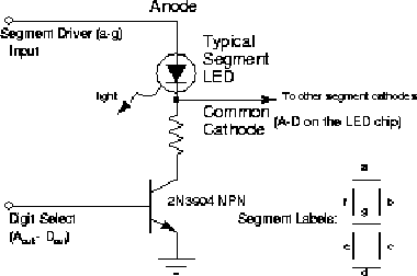
The LED display accepts as input the a through g lines, the Aout through Dout digit select control lines, and gratuitous controls for making colons and dots appear should you want to make a fancy clock (for a bonus point - make your stopwatch output seconds instead of ms with the appropriate decimal place appearing). The seven segment input lines are the actually the LED segment anodes. The chip is “common cathode”, so the cathodes of all seven segments of a digit are tied together at the appropriate A through D digit select line. To make a segment of a digit light up, the appropriate segment line is enabled powering the LED's anode, and the digit's common cathode digit select line is tied to ground so current flows and the LED segment lights up. Use a 2N3904 NPN transistor as a switch to ground, controlled by the counter chip's digit select line and including a current limiting resistor to control whether or not the cathode is grounded for a given digit (see figure).

Draw a box diagram of your circuit showing how it works. Also draw a careful schematic listing pin numbers on the wires. Record your experiences designing, testing, and debugging the thing, and be sure to draw schematics for extra circuit elements you might have to add in order to divide a voltage, debounce a switch, or whatever.
Check your new timer against your wristwatch or the wall clock. If it is running fast or slow, how can you easily adjust the timing? Measure how fast your thumb is by seeing how long it takes for to you start and stop the clock. Take five measurements of this and comment on your consistency or lack thereof. What problems with the circuit could lead to very misleading times? Have you already corrected such problems, or how would you go about doing so?